THE PROCESS
HARDWARE AND TOOLS USED
- Laser cutter
- 3D Printer
- Rhinoceros 3d
- 6mm Birch Plywood
MECHANICAL DESIGN
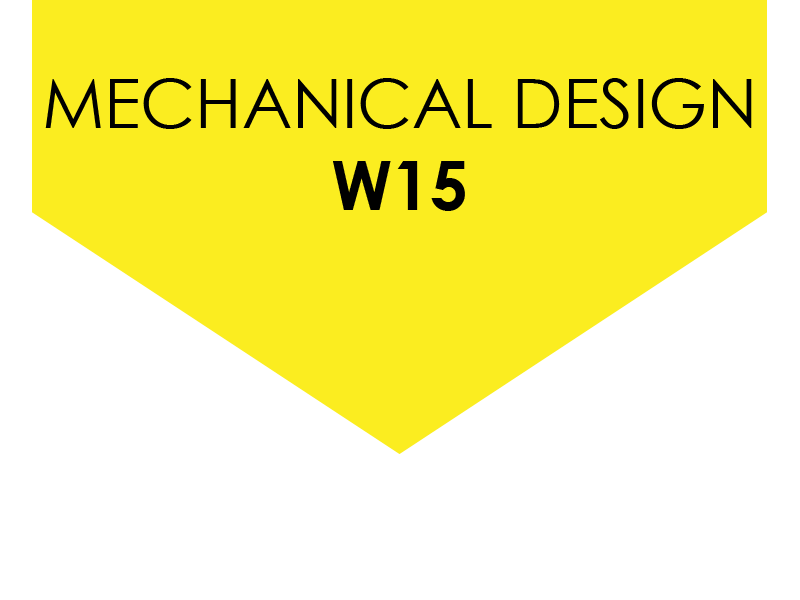
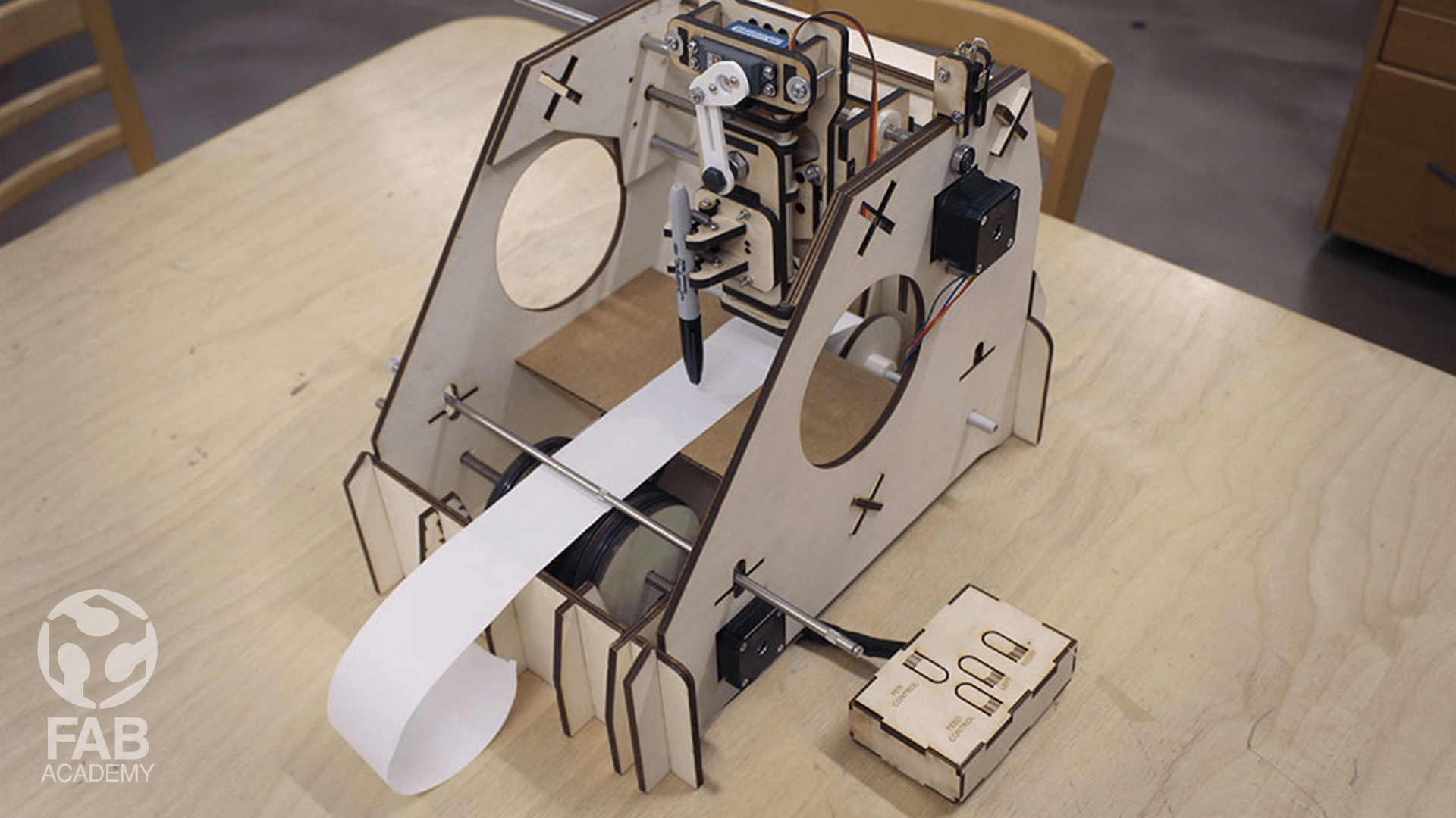
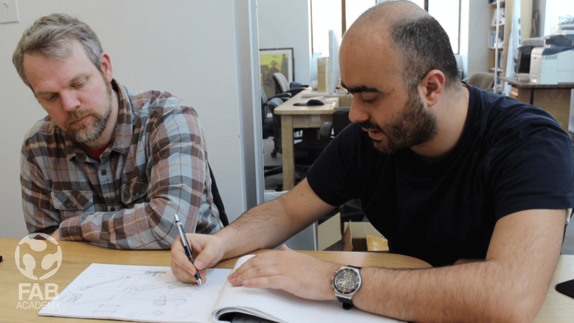
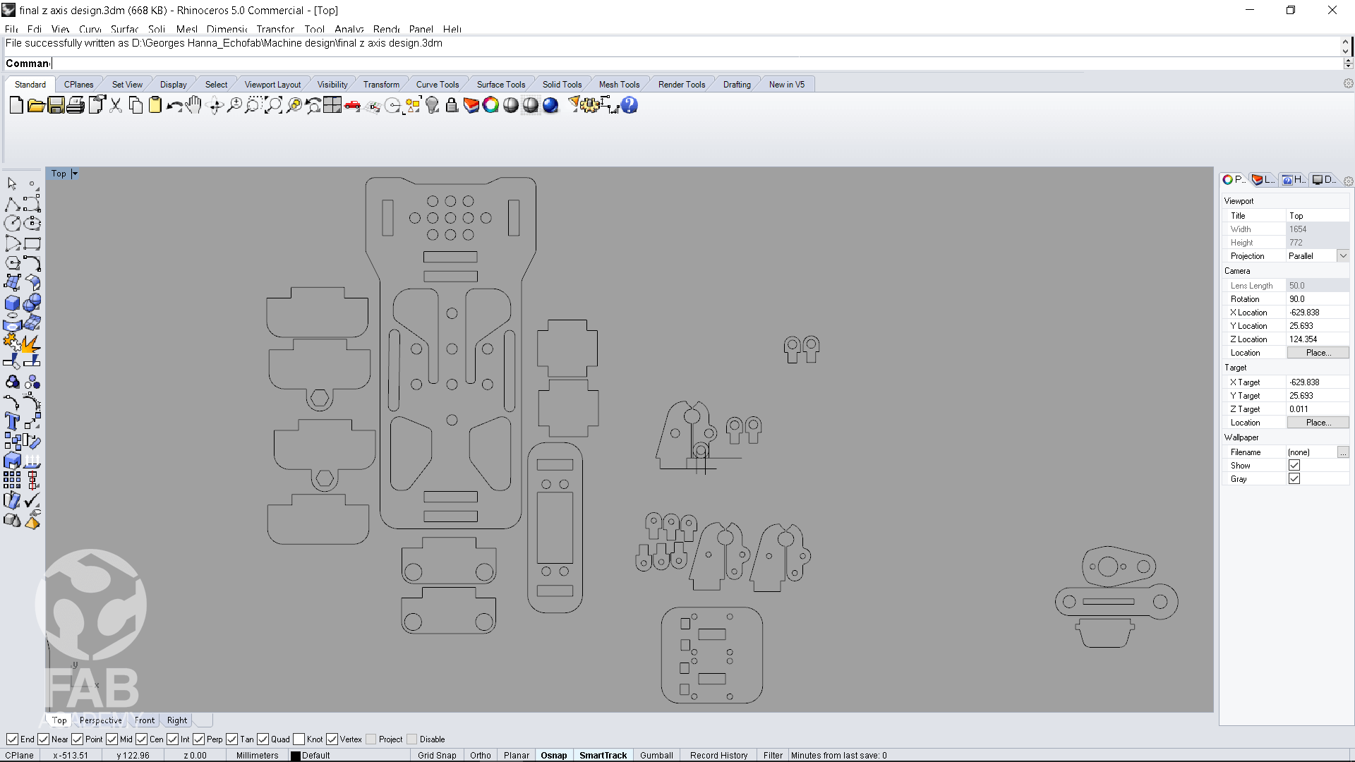
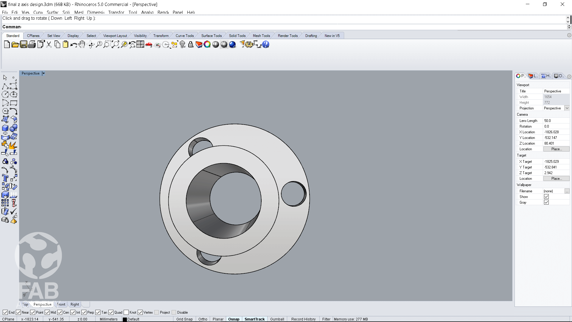
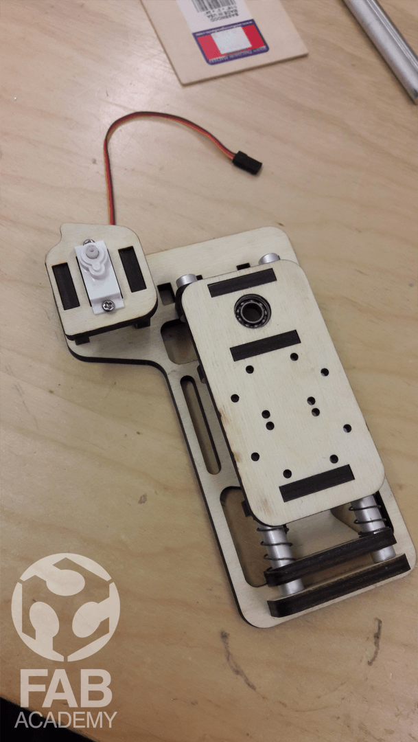
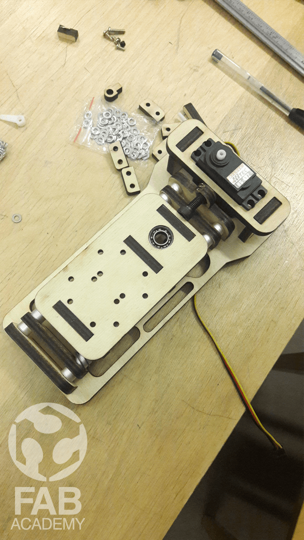
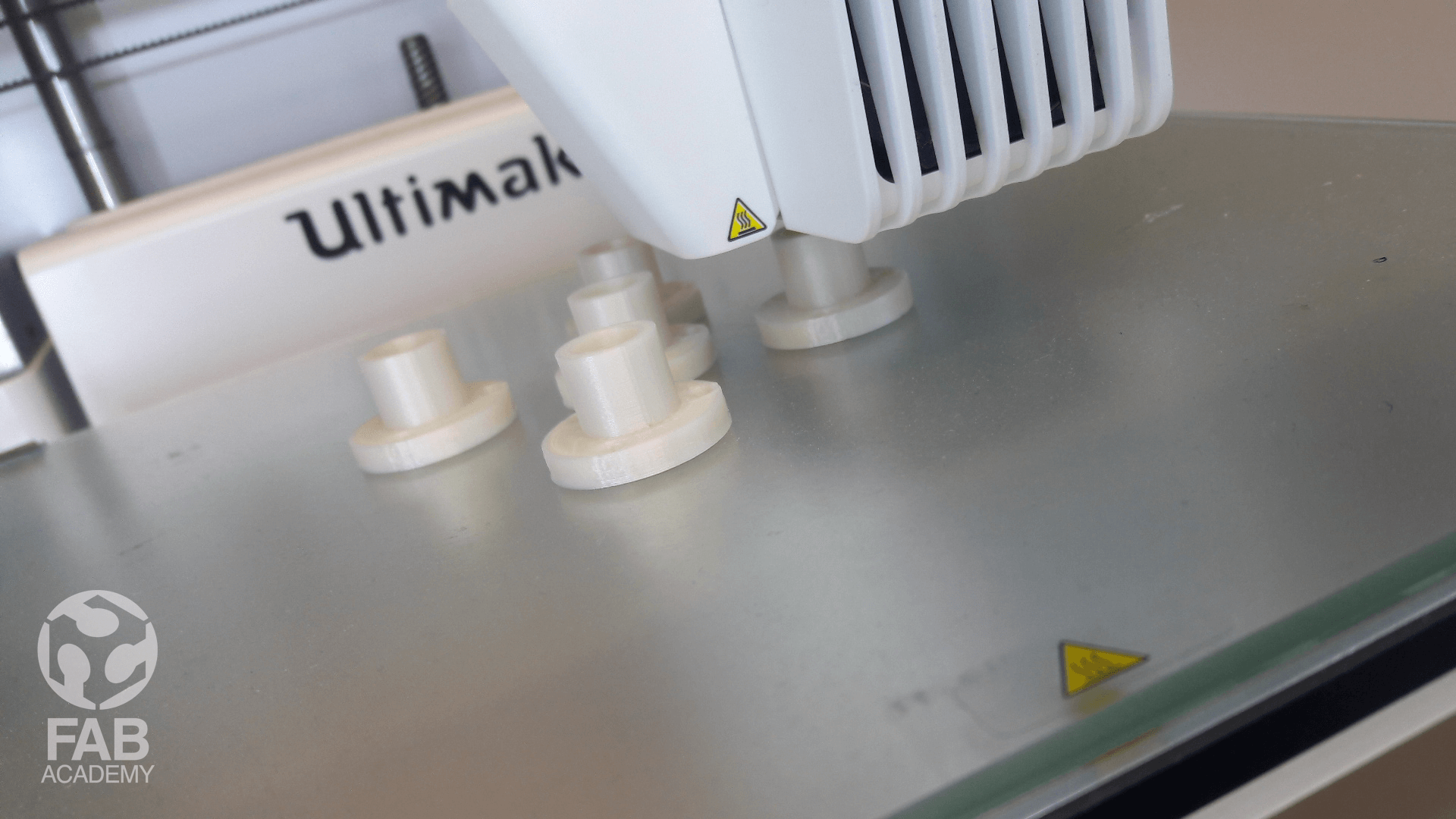
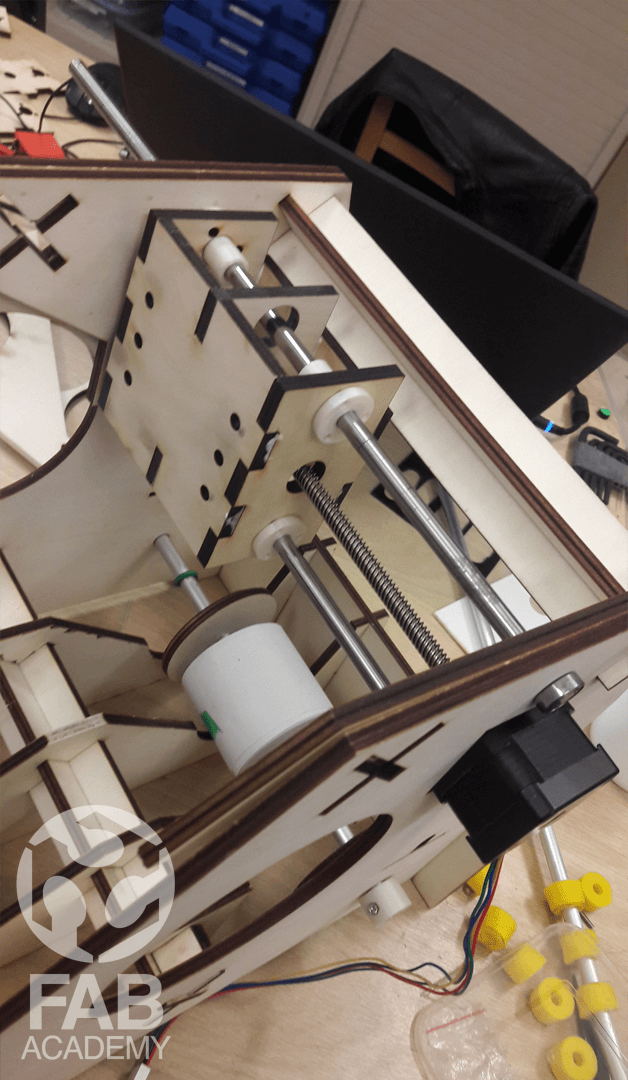
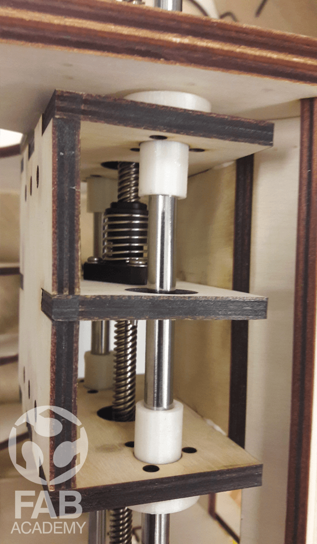
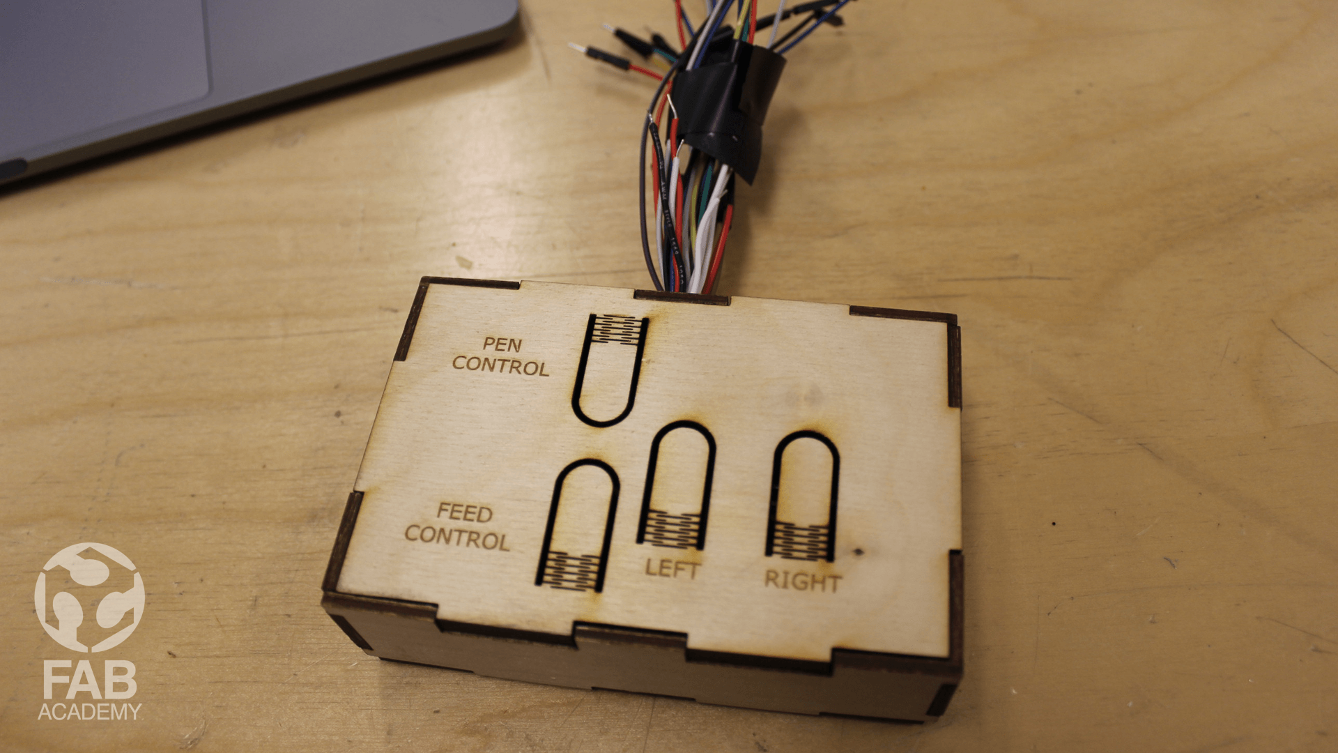
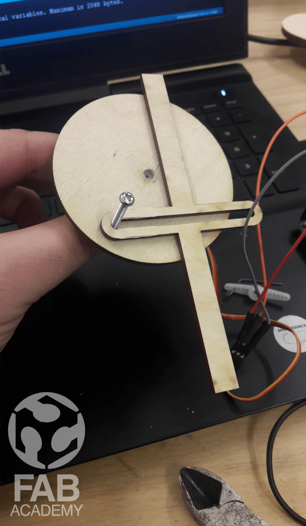
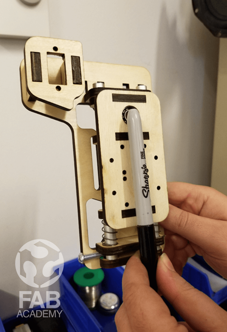
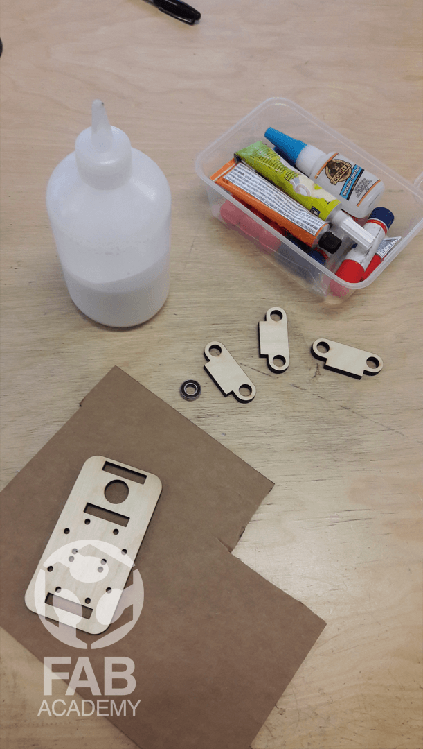
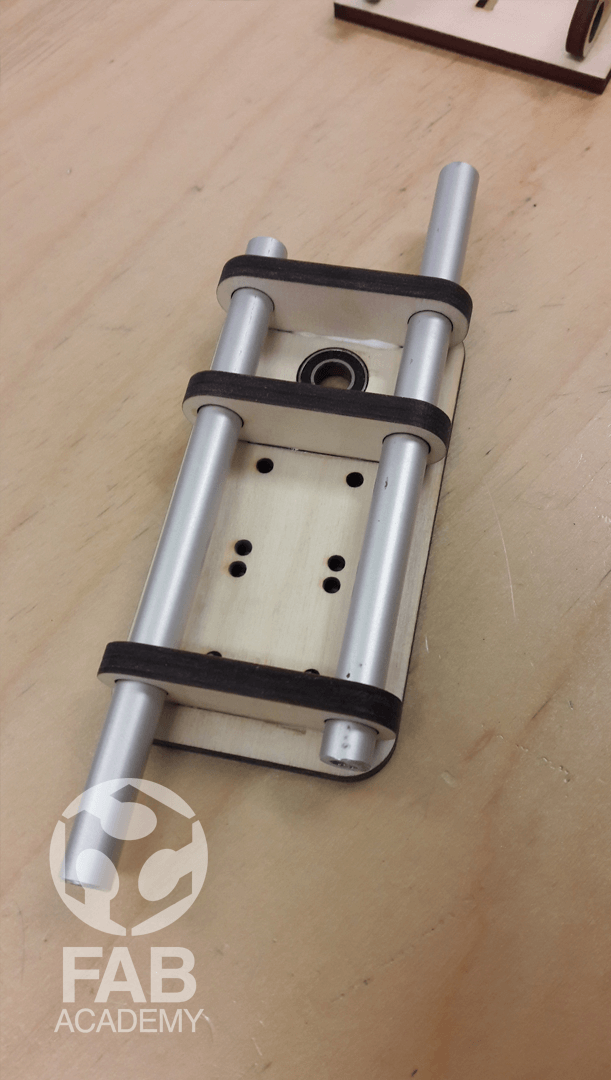
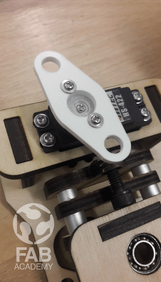
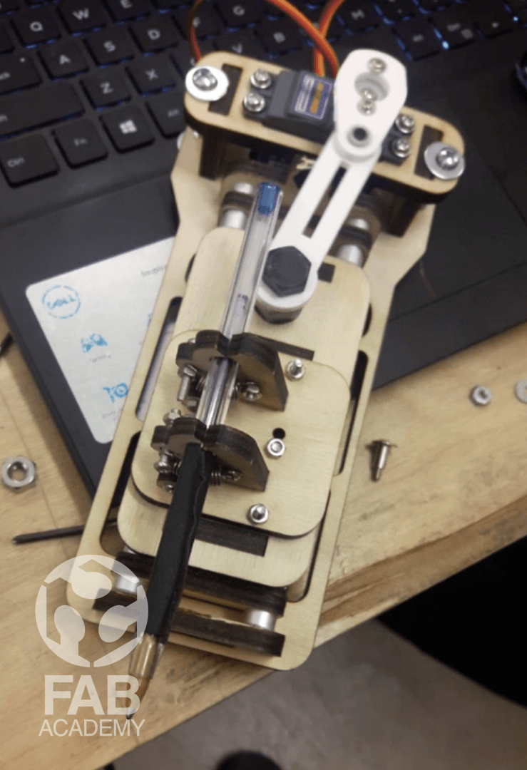
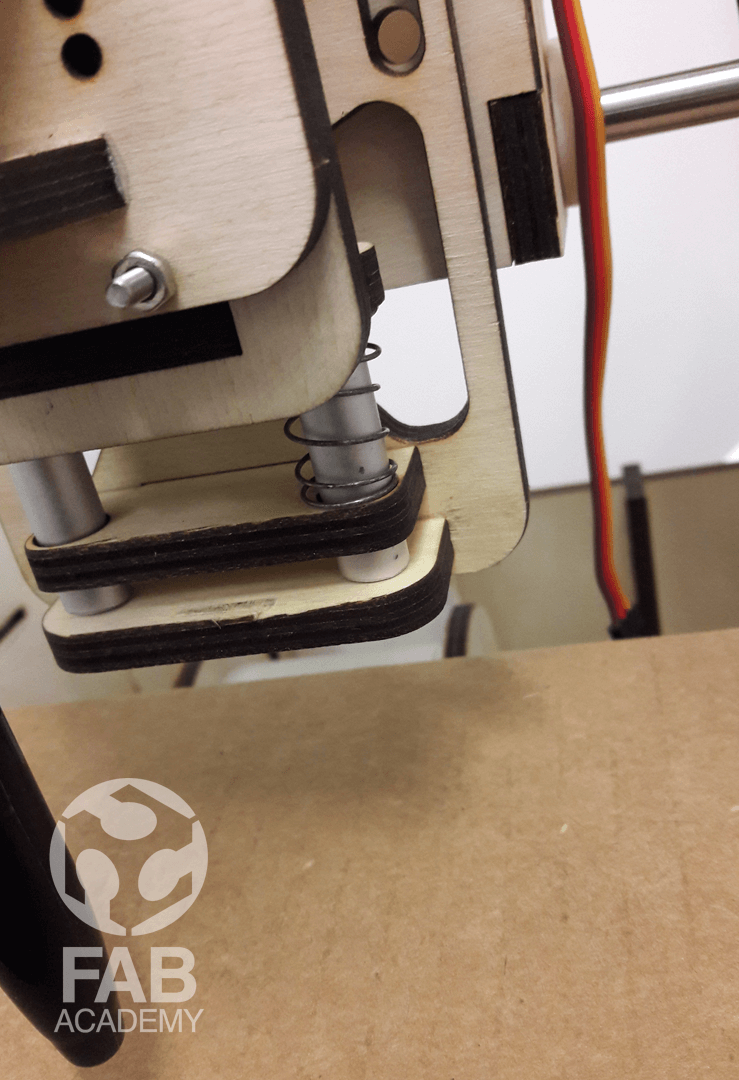
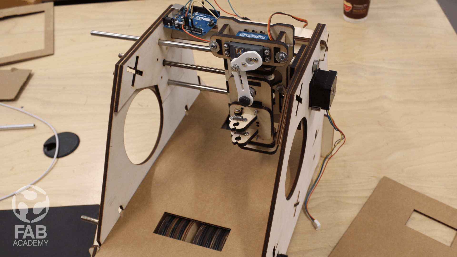
The mechanical design and the machine design assignments were my favorite assignment since they were a group assignment and we had to work all together as a one team in order to achieve mainly 2 goals the first goal was bring our machine to life and to meet our deadline . Initially for this project we develop to do list in order to break the project into manageable tasks to be divvied up among us and we all agreed on the below : - I will be responsible on working on the end effector - Alec Mathewson will be resorbable on working on machine body, feed mechanism - Marc lemaire - will be resorbable on working x-axis and electronics - Geoffroi Garon-Épaule was responsible on documenting the process, making and pushing the presentation online. To start with kicking off our project first we had to sketch many ideas quickly on paper to see which one is doable and which one is not as I noticed that most of our ideas in our first brainstorm session were related to art and drawing machines for instance one of the ideas was making a drawing machine that draws shapes on a rotating circular shaped paper another ideas was making drawing machine that uses a funnel system that drop ink and sand plus glue on a rolling paper and the last idea we had was attaching a sharpie pen to the machine but we were not totally sure that this would be our final idea that we want to proceed with. As mentioned before In our first brainstorm session we divided the tasks among us and my task was working on the mechanical parts related to the z axis and developing a funnel valve mechanism that can drop ink and sand while the machine is working but after a couple of days we changed the idea and we decided to build a pen holder effector that hold a pen. To build the pen holder effector I used all the available materials and resources that we had at our FABLAB in order to speed up the process since we had a very tight deadline and many other assignments to be done. As mentioned before In our first brainstorm session we divided the tasks among us and my task was working on the mechanical parts related to the z axis and developing a funnel valve mechanism that can drop ink and sand based on the user input but after a couple of days we changed the idea and we decided to build a drawing machine that has a pen holder effector that moves up and down and we wanted the machine simply to draw on rolling paper. Based on that first I started by sketching out the idea on paper just to visualize and make it clear as much as possible and then I started designing different prototypes using Rhinoceros 3D . I decided to use Rhinoceros 3D because for 2D drafting I believe it has a much faster workflow than other CAD software. However, Building the Z axis was a really challenging process the first change was making the whole part slide freely without any liner bearing and the 2ndchange was moving the Z axis down and up without using a lead screw. To solve these challenges I decided to use a servo motor for pushing the pen down and up and in order to convert the rotational movement of the servo to liner movement and I used a customized linkage mechanism that was made out of 3 mm acrylic sheet and for cutting the sheet I used the laser cutter. The end results were super high end and precise. In the first prototype as you see in image # 06 I placed the servo on the left side on the pen holder but after I saw Alec and Marc assembling the machine I found that it was not a good idea to place it on the side because it was really wide and it will limit the X Axis travel distance later on that’s why after a short conversation with my friends we all agreed that it would be much better if we place the servo directly above the pen holder. Based on that I readjusted the files and started cutting all the wooden parts using the laser cutter machine. Once all the parts were cut I started assembling them as shown in images # 17 & #18. As for making the whole pen holder travel down and up smoothly along the Z Axis without using any plastic spacers we used 2 aluminum pipes along with 3 wooden parts that were positioned and aligned vertically precisely as shown in image # 18 this mechanism helped me a lot with reducing the friction and getting a really smooth movement . As a result, It was so easy for the servo to push and pull the whole structure . In addition to that and in order to make the pen flexible when pushing down I decided to use a metal spring which was positioned directly on the lower part of the pen holder as shown in image # 21 After I was done with the pen holder effector I started working on the X Axis In ordered to be able to attach the pen holder effector to it. Image # 10 shows the X Axis I made. The design of the X Axis was pretty easy comparing to the Z Axis the only missing elements that we did not have at our Fablab were the wheel spacers to overcome this issue we used the 3D printer to print some 3D spacers as shown in image # 08 After that I had to assemble all the parts together and attach the Pen Holder Effector to the machine’s X Axis using 4 screws. As for the X Axis movement, It was fully controlled by a lead screw which was contacted to a stepper motor . Beside working on the pen holder effector I also worked on the control console unit which was connected to our machine via cables as shown in image # 11 For making the control console I used press fit joints for joining the wooden parts together and for making the buttons I used kerf bending technique for making the wooden buttons fixable and functional at the same time. Overall I believe that all of us did a great job on this project and I was super happy to see how we were able by using 2 different CAD software to fabricate all the parts and assemble them together perfectly and we were all ready to move on to the next assignment which is machine design in ordered to bring our machine to life by programing and wiring all the electronic component together.
DOWNLOAD SECTION
+ Drwaing machine_THE PEN HOLDER EFFECTOR.3dm DOWNLOAD .
+ Drwaing machine_THE PEN HOLDER EFFECTOR.dxf DOWNLOAD .
GROUP PAGE LINK
+ YOU CAN CAN CHECK OUR GROUP PAGE BY CLICKING HERE.